

Attention
The manual should be read cover
to cover once prior to beginning installation
CAUTION:
- This product must be installed by well-trained skilled personnel in compliance with the safety regulations the field of residential and commercial swing gate opener devices. Unqualified personnel may damage the instruments And cause harm to the public.
- Electric Power must be disconnected prior to installation, or performing any maintenance.
- Please read the manual carefully before installation. Incorrect installation or misuse of product may cause seriously damage to users and property.
- If the electric cable is damaged or broken, it must be replaced by a whole and properly insulated wires, to avoid electric shock or any hazardous environments.
- Keep the wireless transmitters out of children reach.
- Do not allow children or other individuals to stand by the path of the motor arms or the path of the gates while in operation.
- Do not use the remote wireless transmitters when the gates are out of sight.
- Do not install the products in corrosive, inflammable, and/or explosive environments.
- Avoid installing the motor arm where the override manual release key is exposed to the public.
Tools Required

I. Configuration of Swing Gate Opener PKM-C01 Dimensions are in mm

Figure 1
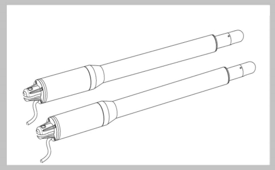
Nomenclature of Swing Gate Motor

Figure 2
Item 1: Post Rear Fixed Bracket
Item 2: Gate Front Fixed Bracket
Item 3: 300mm Extended Arm
Item 4: Motor Box
Item 5: Power Cable
Open the gate manually: Release by spanner then lift it.

Figure 3
Item 1: Gate
Item 2: Manually spanner
Item 3: Release by spanner then lift it and separate the motor from gate
II. Swing Gate Opener Features & Options:
- In case of power failure: Use the manually spanner to release to separate the motor and gate, open or close the gate manually.
- When Gate is Obstructed: Gate stops .
- Optional: The Gate Opener Controller can be connected to a solar system, a flashlight warning, a photocell, back up battery, keypad and other access control devices.
- Speed Control: Gate opening and closing speed can be adjusted.
- Gentle Start: The Gate Opener is equipped with a soft start function.
- Auto Close: The Gate Opener System is equipped with Auto close function with adjustable closing time delay.
- Single or Dual Gate: Either Single or Dual Swing Gate can be opened.
- Multiple Remote Transmitters: The Controller can easily accommodate several unique extra remotes to control the swing gate opener
- Battery Back Up: DC 24V back up battery can be incorporated
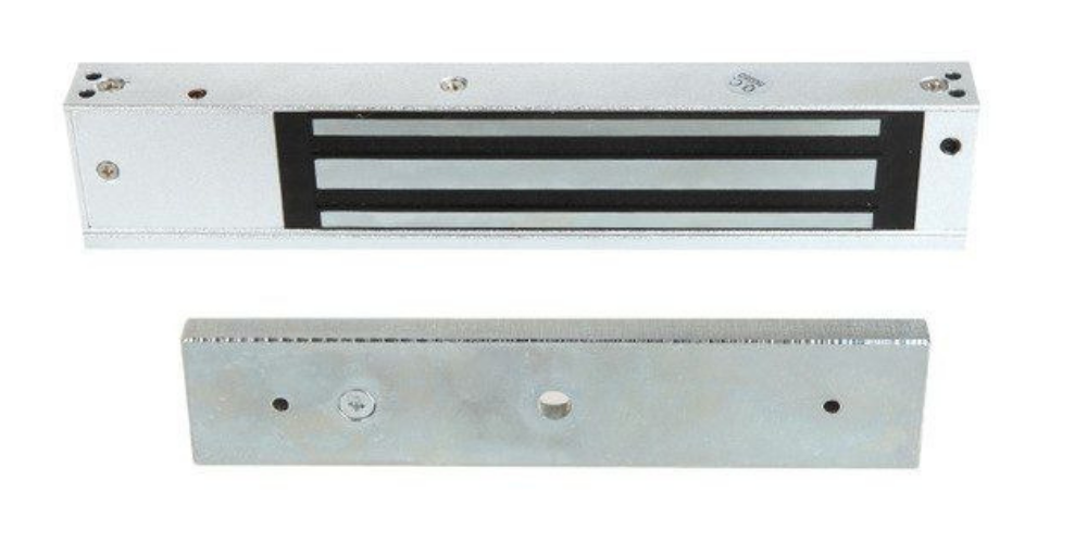
- Optional Devices: DC 24V Gate Lock, photocell ,keypad , photocell, push button, large size or small size control box.
- The Gate Opener can be configured to allow smooth noiseless operation.
- The Gate Opener can be configured to enable open condition as default, or close condition as default depending on the placement of the provided hardware bracket brackets.
III. Technical Specifications
|
Motor voltage: 12VDC 40W |
Input power:220VAC±10%/120VAC±10% |
|
Rotational speed:200 RPM |
Arm's extended speed:1.6 cm/s |
|
Arm's max travel:300 mm |
Continue running time: 5 minutes |
|
Max single-leaf length: 1.5meters |
Max single-leaf weight:150 KG |
|
Environment Temperature:-45°C ~ +50°C |
Protection Class:IP55 |
|
Max gate open angle: 110 degree |
Dual Swing Gate Gross weight : 13KG |
IV. Preparing The Installation Site:

Figure 4
Item Nomenclature
- Wireless Transmitter 4. Control Box
- Rubber Stopper 5. Photocell Electric Sensor
- Swing Gate Opener Motor 6. Flash Light Alarm ( Optional )
V. Rear Bracket Installation Alternatives to Gate Posts

Figure 5
1. Construction Drill and Bolts, Figure 5 right:b. Locate the 4 Slotted Holes Post Bracket above the Drilled Holes
c. Weld the Motor Bracket to the Post Bracket
a. Locate the 4 Slotted Holes of the Post Bracket above the End of U Bolts
b. Apply the Appropriate Screws
c. Place the Motor Connecting Bracket and Tighten with the Provided Screws
4. Adjusting different angles of Rear Bracket Fixed Plate to fit different
Installing condition.

Figure 6

Figure 7
Figure 7 left, Power Cable And Rain Figure 7 right, Power Cable And Rain
Drainage Aperture Placed Correctly Drainage Aperture Placed Incorrectly
1 Post Rear Fixed Bracket 3 Rain Drainage Aperture
2 Lock in 4 Power Cable
Notice: Incorrect Installation, Figure 7 right:
Cable must not be installed above the motor arm. It may pinch and strip the cable and causes electric shock. Follow correct installation as shown in Figure 7left.
VII. Installation of Extended or Retracted End Motor Arms to Gates:

Figure 8
A. Drill 2 Holes of 10.2mm Diameter With Space 68mm Between 2 HolesC. Place the End Motor Bracket to the Gate Bracket using the Appropriate Bolts and Tighten Properly(Please note these bolts used to fixed front bracket to the gate are not provided due to the thickness of each gate is different)
VIII. Brackets Height :

Figure 9
gate bracket height. Failing to ensure accurate common heights will cause the motor arm to bend leading to failure. Also, the force to push or pull the gate will be reduced causing the motor to open or close the gates with difficulty or may not operate successfully at all. Severe different in height will damage the motor and the motor arm.
Configuration of Normally Closed Gate Opener System
Installation size(you can adjust the gate degree according to these numbers)

Figure 10
Control board wiring diagram:
Technical Parameters:
- Control Panel Voltage: AC24V, available for 24 V back up battery.
- Applicable Range: Suitable for double arms swing gate opener.
- Encoder For transmitter: customized rolling code.
- Support remote control: Can memorize 50PCS transmitters at most
- Motor character: 24V DC motor x2

- E1 terminal is used for connecting any external device that operates single gate (cycle control the MAIN motor 2 open-stop-close-stop)
- COM terminal is COMMON used for connecting the “ground” of external devices
- E2 terminal is used for connecting any external device that operates double gates (cycle control open-stop-cloe-stop)
- IR is used for connecting photo electric sensor
- COM terminal is COMMON used for connecting the “ground” of external devices
- LAMP - terminal is used for connect lamp - .
- LAMP + terminal is used for connect lamp + .
- LOCK - terminal is used for connect mechnical lock - .
- LOCK + terminal is used for connect mechnical lock +.
NOTE: when gate trigger open signal, then lock output, after lock working 0.5s then gate start working, after more 4.5s, then lock stop output (the complete lock output time is 5s)
- 12V+ terminal is 12V power positive pole output, used for connecting an external device (max output 200mA)
- 12V- terminal is 12V power negative pole output, used for connecting an external device (max output 200mA)
- and 13. Motor1 terminal is used for connecting the motor 1 installed on the gate that opens later and closes first. This terminal connects 1st red wire (counted from your left-hand side to right-hand side)
- and 15. Motor2 Delay terminal is used for connecting the motor 2 installed on the gate that opens first and closes later. This terminal connects 1st blue wire (counted from your left-hand side to right-hand side). NOTE! If for a single gate, the gate motor just can connect the Motor2 Delay terminal.
- Power terminal input is used for connecting the transformer
- Power terminal input is used for connecting the transformer
- 24V battery output is used for connecting the backup battery -
- 24V battery output is used for connecting the backup battery +
Remote control
Button “1” depressed to operate MOTOR 2 single gate; button “2” depressed to operate MOTOR 2 single gate; button “3” depressed to operate double gate; button “4” depressed for alarm output
Program new remote control:
First step:
Press the LEARN button on the control board for about 1 second, the indicator LED would light on then now means have already entered learning
Second step:
Press any button of the new remote control for about 2 seconds, the indicator LED on board starts fast flash 2 times then now means the learning successfully.
Note! After you press LEARN button, if not receive the new remote signal within 8s, indicator LED would turn on and exit learning.
The remote that already learned can not code learning again.
Remove remote control:
Press and hold the LEARN button for about 8 seconds, if indicator LED light on, then now means remove remote successfully.
3. The setting of the control board:
3.1 Travel learning function:When gate in fully open condition, press LEARN button 5 times continuous, indicator LED light on, then the motor will automatic to open and close one cycle. If indicator LED turns off then it means travel learning successfully. The system will automatic to allocate the high speed/ low speed running time.
3.2 Program setting:
3.2.1
For the sensitivity of meet resistance, there is a three-degree jumper for option, it can through adjust the jumper to chooseHeavy: it means used for heavy weight gateMedium: it means used for medium weight gateLight: it means used for the lightweight gate
3.2.2 Dip switch setting:
A. Dip 1 OFF and Dip 2 OFF : it means close the auto close functionB. Dip 3 OFF: it means gate open and gate close delay 3s;
C. Dip 4 OFF: it means when gate motor working, then lamp light on; when gate motor stop, then lamp turn off.

1 comment
Marc
need service teck to check & program solar power double swing gate GALU linear actuator
let me know if this is possible
Leave a comment
All comments are moderated before being published.
This site is protected by hCaptcha and the hCaptcha Privacy Policy and Terms of Service apply.