
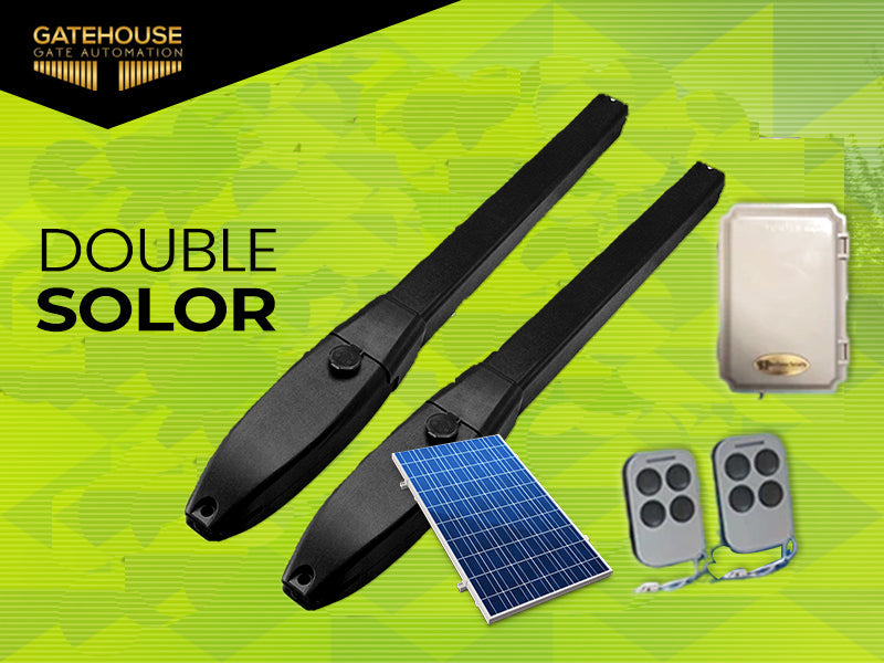
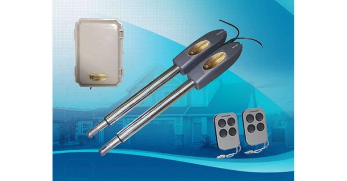

- Product Configurations:

Figure 1 Nomenclature of Swing Gate Motor

Figure 2
Item 1: Post Rear Fixed Bracket
Item 2: Extended Bracket Attached to Gate Structure
Item 3: Gate Front Fixed Bracket
Item 4: 300-400mm Extended Arm
Item 5: Motor Gear Box
Item 6: Power Cable
Item 7: Rear Bracket Fixed Plate Main Motor Arm
Override Manual Release Key

Figure 3
- Swing Gate Opener Features & Options:
- In case of power failure: Use the manual override key to release the clutch to open or close the gate manually.
- When Gate is Obstructed: Gate stops .
- Optional: The Gate Opener Controller can be connected to a solar system, a flash light warning, a photocell, back up battery, keypad and other access control devices.
- Speed Control: Gate opening and closing speed can be adjusted.
- Gentle Start: The Gate Opener is equipped with a soft start function.
- Auto Close: The Gate Opener System is equipped with Auto close function with adjustable closing time delay.
- Single or Dual Gate: Either Single or Dual Swing Gate can be opened.
- Multiple Remote Transmitters: The Controller can easily accommodate several unique extra remotes to control the swing gate opener
- Battery Back Up: DC 24V back up battery can be incorporated
- Optional Devices: DC 24V Gate Lock ,photocell ,keypad , photocell,push button,large size or small size control box.
- The Gate Opener will have smooth noiseless operation.
- The Gate Opener can be configured to enable open condition as default, or close condition as default depending on the placement of the provided hardware bracket brackets.
III.Technical Specifications
|
Motor voltage: 24VDC 60W |
Input power:220VAC±10%/120VAC±10% |
|
Rotational speed:300 RPM |
Arm's extended speed:2.4 cm/s |
|
Arm's max travel:300 mm |
Continue running time: 5 minutes |
|
Max single-leaf length: 2.5meters |
Max single-leaf weight:300-350 KG |
|
Environment Temperature:-20°C ~ +50°C |
Protection Class:IP55 |
|
Max gate open angle: 110 degree |
Dual Swing Gate Gross weight : 17.5kg |
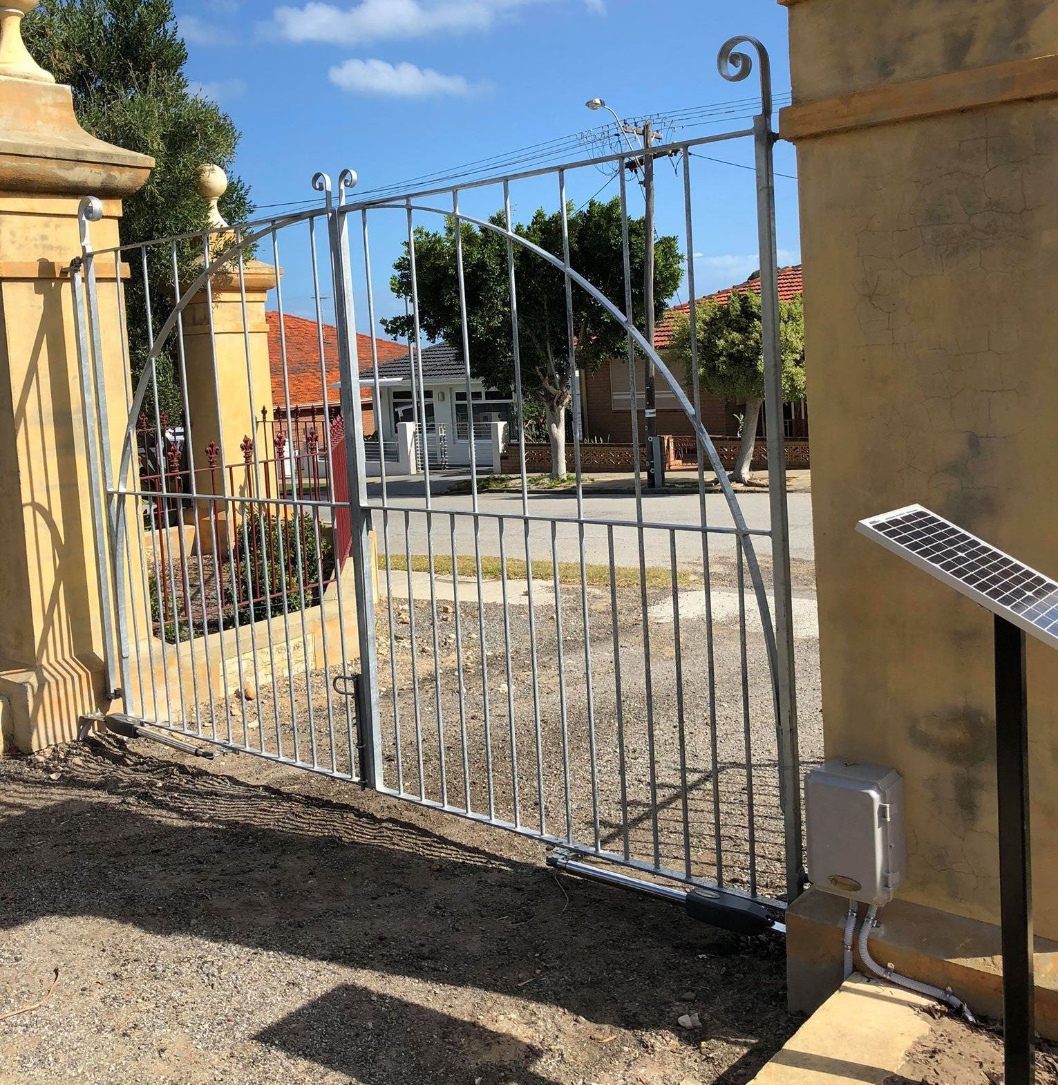
- Preparing The Installation Site:

Item Nomenclature Figure 4
- Wireless Transmitter
- Rubber Stopper
- Swing Gate Opener Motor
- Control Box
- Photocell Electric Sensor
- Flash Light Alarm ( Optional ) V.

- Adjusting different angles of Rear Bracket Fixed Plate to fit different Installing condition.
 Figure 6
- Install the Motor Fixed-End to the Gate Post-Bracket
- Ensure the Override Motor Key Post to face the ground away from the view of the public.

Figure 7
- Once the Lock Pin and the Lock Washer are inserted between the Fixed End Motor and the Gate Post Bracket ensure the power is not connected
- Insert Override Manual Key
- Turn the Key Clockwise to disengage the motor clutch to enable manual operation of gate.

Figure 8
Figure 8 left, Power Cable And Manual Figure 8 right, Power Cable And Manual
Override Release Placed Correctly Override Release Placed Incorrectly
- Post-Rear Fixed Bracket
- Rear Bracket Fixed Plate Main Motor Arm
- Lock Pin
- Rain Drainage Aperture
- Washers and Lock Nuts
- Power Cable
Cable must not be installed above the motor arm. It may pinch.
Also the manual override release must be located face to the ground. Follow correct installation as shown in Figure 8 left.
VIII. Installation of Extended or Retracted End Motor Arms to Gates:
 A. Drill 2 Holes of 10.2mm Diameter With Space 68mm Between 2 Holes
B. Locate the 2 Slotted Holes Gate Bracket above the Drilled Holes
C. Place the End Motor Bracket to the Gate Bracket using the Appropriate Bolts and Tighten Properly(Please note these bolts used to fixed front bracket to the gate are not provided due to the thickness of each gate is different)
D. Insert the Lock Pin and Clamping Washers
Ensure that the Post bracket height is in the same exact level with the gate bracket height.
Severe difference in height will damage the motor and the motor arm.
Configuration of Normally Closed Gate Opener System

Figure 11
A: The Distance between the Gate Post Edge and the Fixed Motor Hinge
B: The Distance between the Gate Hinge and the Centerline of the Motor Hinge
C: The Distance between the Gate Hinge and the Maximum Distance of the Retracted Motor Condition
Configuration of Normally Open Gate Opener System

Figure 12
A: The Distance between the Gate Post Edge and the Fixed Motor Hinge
B: The Distance between the Gate Hinge and the Centerline of the Motor Hinge
C: The Distance between the Gate Hinge and the Maximum Distance of the Retracted Motor Condition
Control board wiring diagram:
 Figure 13
- 2 SIDE terminal is used for connecting any external device that operates double gate
- COM terminal is COMMON used for connecting the “ground” of external devices
- 1 SIDE terminal is used for connecting any external device that operates single gate 4. Swipe Card terminal is used for connecting any external devices that will operate to open the gate
- COM terminal is COMMON used for connecting the “ground” of external devices
- Infrared terminal is used for connecting photo electric sensor
- 12V DC output is used for connecting photo electric sensor (Continuous output current <=200mA)
- 24V battery output is used for connecting the back up battery +
- 24V battery output is used for connecting the back up battery -
- 24V DC output is used for connecting external device. (such as photo electric sensor, max current output 1A)
- GND is used for connecting the “ground” of external devices
- 24V DC lamp output is used for connecting flash light +.
- 24V DC lamp output is used for connecting flash light -.
- 24V DC lock output—the NF terminal which used for connecting the electric lock
- COM is COMMON used for connecting the “ground” of lock
- 24V DC lock output—the NA terminal which used for connecting the magnetic lock
- 24V DC alarm output
- 24V DC alarm output
19 and 20. Motor1 terminal is used for connecting the motor 1 installed on the gate that opens later and close first. This terminal connect 1st red wire (counted from your left hand side to right hand side)
21 and 22. Motor2 Delay terminal is used for connecting the motor 2 installed on the gate that opens first and close later. This terminal connect 1st blue wire (counted from your left hand side to right hand side). NOTE! If for single gate, the gate motor just can connect the Motor2 Delay terminal.
- AC24V input is used for connecting the transformer
- AC24V input is used for connecting the transformer
- digital display is used for showing you the setting data
- INC+ is used for figure increase when setting the data
- FUN is used for store the data
- DEC- is used for figure decrease when setting the data
- Learning button is used for program/remove remote
Remote control
Button “1” depressed to operate single gate; button “2” depressed to operate double gate; button “3” depressed for alarm output Program new remote control:
First step:
Press the LEARN button on the control board for about 1 second, the indicator LED
would turn off, then now means have already enter learning Second step:
Press any button of the new remote control for about 2 second, then digital display would show the remote number while indicator LED on board starts flash four times with one buzzer sound then now means the learning successfully.
Note! After you press LEARN button, if not receive the new remote signal within 5s, indicator LED would turn on and exit learning.
Remove remote control:
Press and hold the LEARN button for about 5 second, if with one buzzer sound and indicator LED light on, then now means remove remote successfully. Setting of the control board:
After power on, digital display will self-check from 00-99 with buzzer sound.
If indicator LED light on, buzzer stop sounding, it means the system is normal.
Basic operation method:
Press and hold the [ FUN] button until the digital display shows PO. Now you enter the menu setting. You could through adjust the [INC+] [DEC-] to increase or decrease the serial number or numerical value. After data adjust well then press [ FUN] to store the data. With one sound of buzzer, the store successfully. After store the data, the digital display would still on the menu number you just set, if you need to enter next menu setting, please press [INC+] or [DEC-] to choose and confirm with [FUN] to enter the menu number you want to set. Such as after you store the P0 value and press [FUN] to store it, then now the digital display would still show the number P0, and if you want go further to adjust P1, please press one [INC+], then digital display show P1, later press [FUN] to enter the P1 setting. And if you not need to enter next menu setting, you could press [LEARN] button to exit the menu setting.
- To set the soft start time:
When digital display indicate P0, the gate opener is on the soft start time setting. The soft start time adjustable from 0-6s, 0s means close the soft start time, max soft start time 6s. Each time you press and release the [INC+] button, the figure increase by 1; each time you press and release the [DEC-] button, the figure decrease by 1. Press the [FUN] button to store the data when the soft start time chosen, then the soft start time setting finished (Factory set 2s).
- To set the level of stall force:
2a-- When digital display indicate P1, the gate opener is on Motor 1 low speed running stall force adjustment. There is 0-20 levels for optional, each time you press and release the [INC+] button, the figure increase by 1; each time you press and release the [DEC-] button, the figure decrease by 1. Press the [FUN] button to store the data when the stall force level chosen, then the stall force of Motor 1 low speed running stall force adjustment finished. (factory set 6 level)
2b-- When digital display indicate P2, the gate opener is on Motor 1 high speed running stall force adjustment. There is 0-20 levels for optional. Each time you press and release the [INC+] button, the figure increase by 1; each time you press and release the [DEC-] button, the figure decrease by 1. Press the [FUN] button to store the data when the stall force level chosen, then the stall force of Motor 1 high speed running stall force adjustment finished. (factory set 10 level)
2c-- When digital display indicate P3, the gate opener is on Motor 2 low speed running stall force adjustment. There is 0-20 levels for optional. Each time you press and release the [INC+] button, the figure increase by 1; each time you press and release the [DEC-] button, the figure decrease by 1. Press the [FUN] button to store the data when the stall force level chosen, then the stall force of Motor 2 low speed running stall force adjustment finished. (factory set 6 level)
2d-- When digital display indicate P4, the gate opener is on Motor 2 high speed running stall force adjustment. There is 0-20 levels for optional. Each time you press and release the [INC+] button, the figure increase by 1; each time you press and release the [DEC-] button, the figure decrease by 1. Press the [FUN] button to store the data when the stall force level chosen, then the stall force of Motor 2 high speed running stall force adjustment finished. (factory set 10 level)
- To set the high speed running time:
When digital display indicate P5, the gate opener is on high speed running time setting. There is 0-33s for optional. 0s means without high speed running, gate opener would keep running in slow speed. Max high speed running time 33s. Each time you press and release the [INC+] button, the figure increase by 1; each time you press and release the [DEC-] button, the figure decrease by 1. Press the [FUN] button to store the data when the high speed running time chosen, then the high speed running time setting finished. (factory set 5s)
- To set the auto close time after swipe card:
When digital display indicate P6, the gate opener is on auto close time setting ( NOTE! this auto close time just means the auto close function which realize through external device-). There is 0-99s for optional. 0 means the gate opener would not auto close after swipe card. Max auto close time after swipe card 99s. Each time you press and release the [INC+] button, the figure increase by 1; each time you press and release the [DEC-] button, the figure decrease by 1. Press the [FUN] button to store the data when the auto close time after swipe card chosen, then the auto close time after swipe card finished. (factory set 10s)
- To set the interval time between gates:
5a. When digital display indicate P7, the gate opener is on open interval time setting. There is 0-10s for optional. 0s means double gates open simultaneously. “1” means the Motor 1 start to open 1 second before Motor 2 start to open. Max open interval time 10s. Each time you press and release the [INC+] button, the figure increase by 1; each time you press and release the [DEC-] button, the figure decrease by 1. Press the [FUN] button to store the data when the open interval time chosen, then the open interval time setting finished. (factory set 0s)
5b. When digital display indicate P8, the gate opener is on close interval time setting.
There is 0-10s for optional. 0s mean double gates close simultaneously. “1” means the Motor 2 start to close 1 second before Motor 1 start to close. Max close interval time 10s. Each time you press and release the [INC+] button, the figure increase by 1; each time you press and release the [DEC-] button, the figure decrease by 1. Press the [FUN] button to store the data when the close interval time chosen, then the close interval time setting finished. (factory set 0s)
- To set auto close time:
When digital display indicate P9, the gate opener is on auto close time setting. There is 0-99s for optional. 0s mean the gate opener would not auto close. Max auto close time is 99s. Each time you press and release the [INC+] button, the figure increase by 1; each time you press and release the [DEC-] button, the figure decrease by 1. Press the [FUN] button to store the data when the auto close time chosen, then the auto close time setting finished. (factory set 0)
- To set lamp/alarm output control:
When digital display indicate PA, the gate opener is on lamp/alarm output control setting. There is 0-3 for optional. “0” means the alarm on monostabillity model and the lamp without voltage output after the gate total close 30s, other time with voltage output. “1” means the alarm on monostabillity model and the lamp would only flash when gate running. “2” means the alarm on bistabillity model and the lamp without voltage output after the gate total close 30s, other time with voltage output. “3” means the alarm on bistabillity model and the lamp would only flash when gate running. Each time you press and release the [INC+] button, the figure increase by 1; each time you press and release the [DEC-] button, the figure decrease by 1. Press the [FUN] button to store the data when the auto close time chosen, then the lamp/alarm output control setting finished. (factory set 0)
- To set lock time:
When digital display indicate Pb, the gate opener is on lock time control setting. The lock control time means the time we could control the lock. There is 0-1 for optional. “0” means the lock control time is 0.5s, “1” means the lock control time is 5s. Each time you press and release the [INC+] button, the figure increase by 1; each time you press and release the [DEC-] button, the figure decrease by 1. Press the [FUN] button to store the data when the lock control time chosen, then the lock time setting finished. (factory set 0)
- To choose single/double gate open:
When digital display indicate PC, the gate opener is on single/double gate open setting. There is 0-3 for optional. “0” means the gate could not open by remote, “1” means just can open one single gte, “2” means can just open two leaf gate, “3” means can open one single gate as well as two leaf gate. Each time you press and release the [INC+] button, the figure increase by 1; each time you press and release the [DEC-] button, the figure decrease by 1. Press the [FUN] button to store the data when the single/double gate open chosen, then the remote button setting finished. (factory set 3)
- To reset:
When digital display indicate Pd, the gate opener is on rest setting. After enter Pd setting, press the [ FUN] to store and then now the reset successfully.
Common questions and answers
- Always have the gates in the closed position at the start. The gates must be free running the whole way and close to level when open and level when closed otherwise it puts excessive load on the motors.
- I suggest using a clamp to fix the brackets on the gate and the post before you drill any holes to see if everything works as it should. If using a typical pipe farm gate, try using a 35mm U bolt on the bottom rail of the gate to connect to.
- Mount the actuator on the gate post, unlock with the key and manually pull out actuator fully. Where the end of the actuator meets the gate is where the bracket should go.
- Check that all control board settings are correct, set to default.
- Connect actuators to control board, single gate to motor 2, double gate to motor 1 and 2
- Connect the power and try a remote, if it opens correctly then fix brackets with screws and bolts.
- If you find the gate is trying to close when it is already closed, then look for small coloured lights by the terminals on the control board where you connected the actuators. When you use the remote to open the gate and a red light comes on then reverse the two wires. If a blue light shows then it is correct.
- If you want to make any changes to motor speed, stall force, soft start etc now is the time to do it.
- Remember to check you have the settings set to auto close if that is what you want, or you will have to use the remote to close the gate.
- If you make any change to the settings different from default, try it a few increases or decreases at a time, not big jumps. Adjust and test, adjust and test. If you get a problem, reset board to factory default, re-clone the remotes and try again…You won’t break anything.
- If you have any accessories like lights, keypad, exit buttons etc and the gate will not work correctly now, then disconnect all accessories and go back to the beginning making sure the basic gate system works well, then start connecting accessories again one at a time checking operation each time you make a change.
- If you are using a solar system, the solar charge controller slides down the left side of the control board, look for the slots. Don’t change the settings of the solar charge controller it is set ready to go. Look at the sheet supplied for solar, how to wire it up and connect to the 24v terminals.
- The batteries lay down not stand up in the control box, or they won’t fit.
- The gate kits are designed to operate 5-6 open/closes per day, any more than that, summer usually ok, but winter you may run out of battery power. You can add an extra solar panel or bigger batteries, or both. Commercial operators use two car or truck batteries and double solar panels.
If you come across any issues during installation, please contact us so we can help 1800 931 597
Best regards,
Graeme

Leave a comment
All comments are moderated before being published.
This site is protected by hCaptcha and the hCaptcha Privacy Policy and Terms of Service apply.